


- Model Number: LM324
- Type: Electronic Device Battery Tester
- DIY Supplies: ELECTRICAL
- Brand Name: TKXEC
- Origin: Mainland China


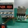
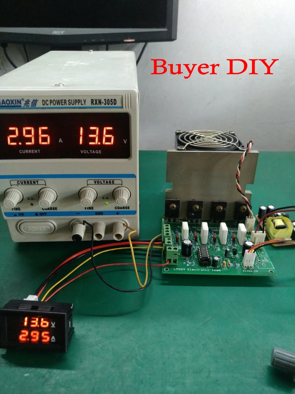
input voltage : 0-15v /0-72V
load current :0-10A/0-2A
The voltage is the range of the power supply voltage value and cannot be adjusted.
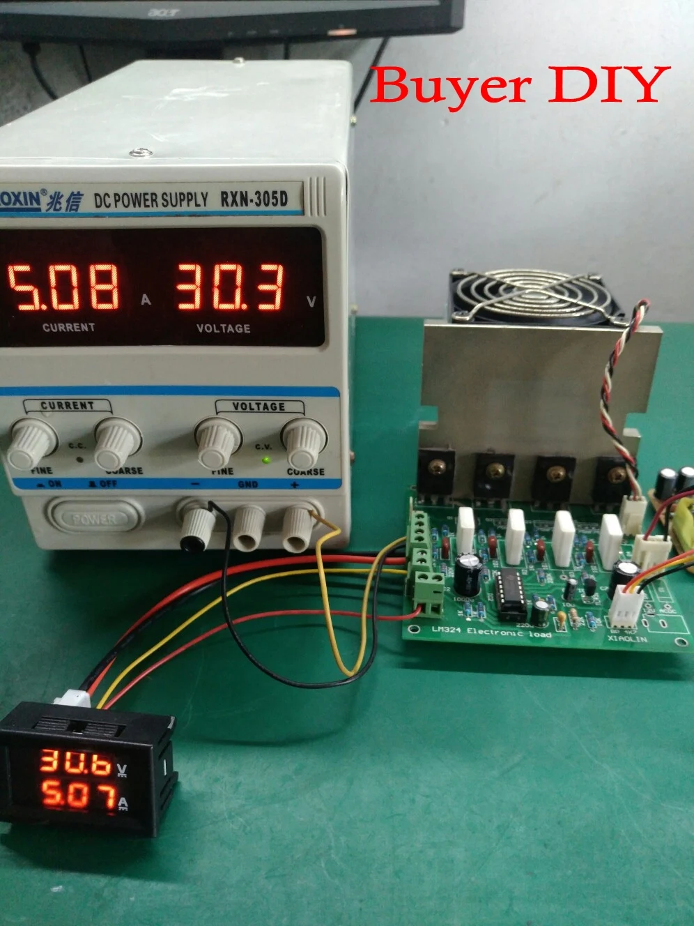
The current is adjustable for this load test. After adjusting the desired value, test with constant current.
Test the maximum discharge current of the power supply, check whether the power supply current is real, and use the power product aging test.
Remarks: How many W are all in the power dissipation of the NMOS tube, and the board voltage is within 300V. You can also increase the power in parallel with multiple blocks.
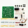
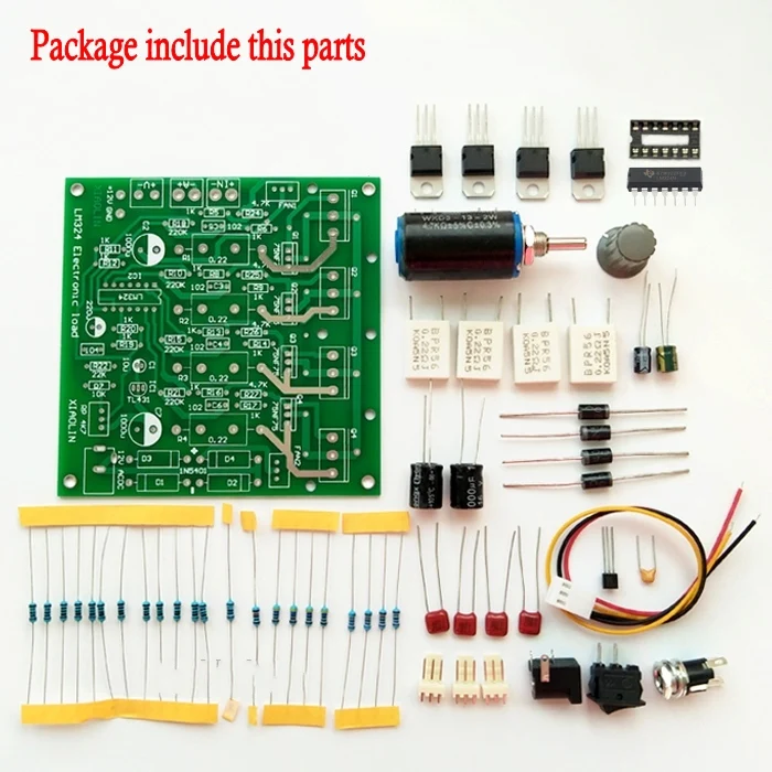
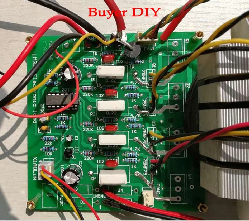
1. The basic circuit form is that TL431 provides reference voltage, sense resistor, LM324 operational amplifier error amplification,
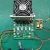
Together with the MOS tube, it forms a constant current circuit. Use 4 MOS tubes with CPU heat sink.
2. Our shop has 4 sets of 110N8F6 110A 80V packaged in T0-220
3. The parameters of the original circuit diagram: 75NF75 75V 75A 150W
4. Substitution: Model 80NF70 IRF3205 HRF3250 IRF1010 IRF2807IRF1405 047an08ao, etc., also available for TO-247 high-power packaging tubes such as IRF 250 260
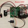
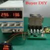
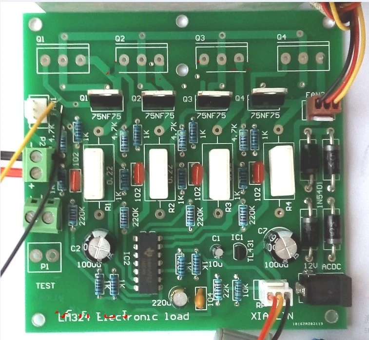
2. When the board is powered by a 12V switching power supply, the wire can be soldered to the right + -.
Or solder the DC seat and use 2 wires to short-circuit the +- solder joint. The 4 rectifier tubes can be welded! ! !
3. The heat sink cannot be connected to the negative metal of the 12V DC seat, and the two cannot be connected to the metal shell at the same time! !
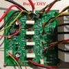
4. When the board is connected to the digital dual display meter, the power supply of the meter header is connected with the small red line on the left end of the board: +12V
Note: Do not connect the thin black wire to GND! (It will be inaccurate if the current is connected)! ! !
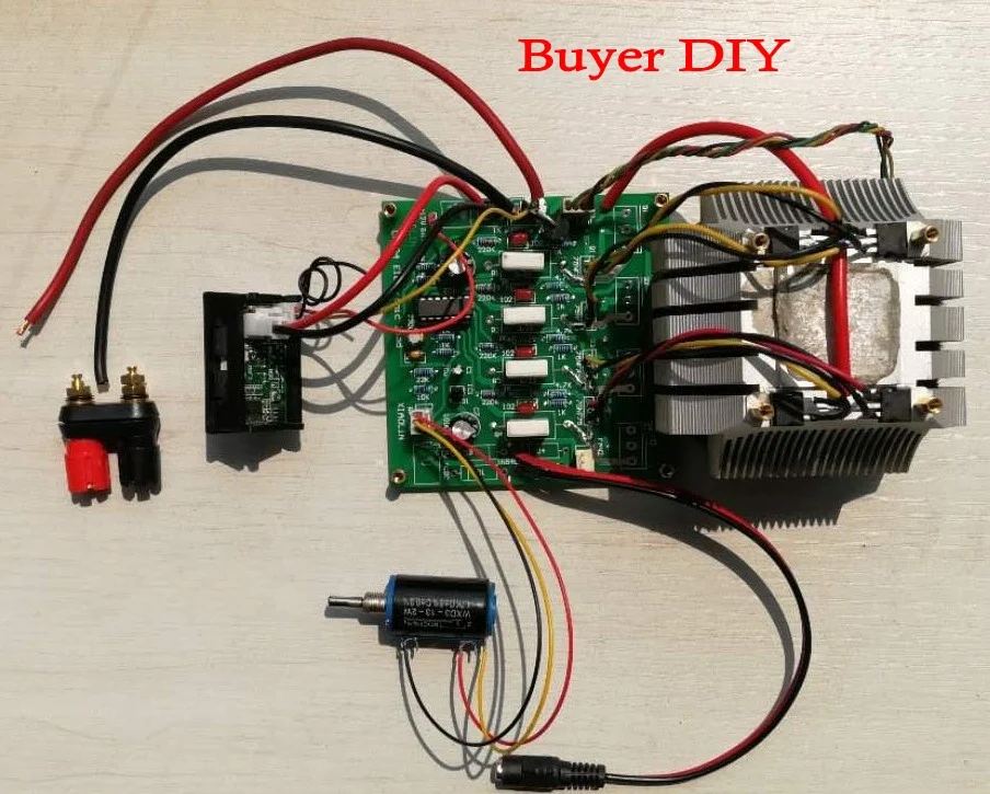
5. A+-the current thick red and black wire connected to the meter head V+ is connected to the thin yellow wire voltage test of the meter head, IN is the test input terminal, and the red and black test terminal is connected to the power supply under test. The FAN terminal is connected to the cooling fan.
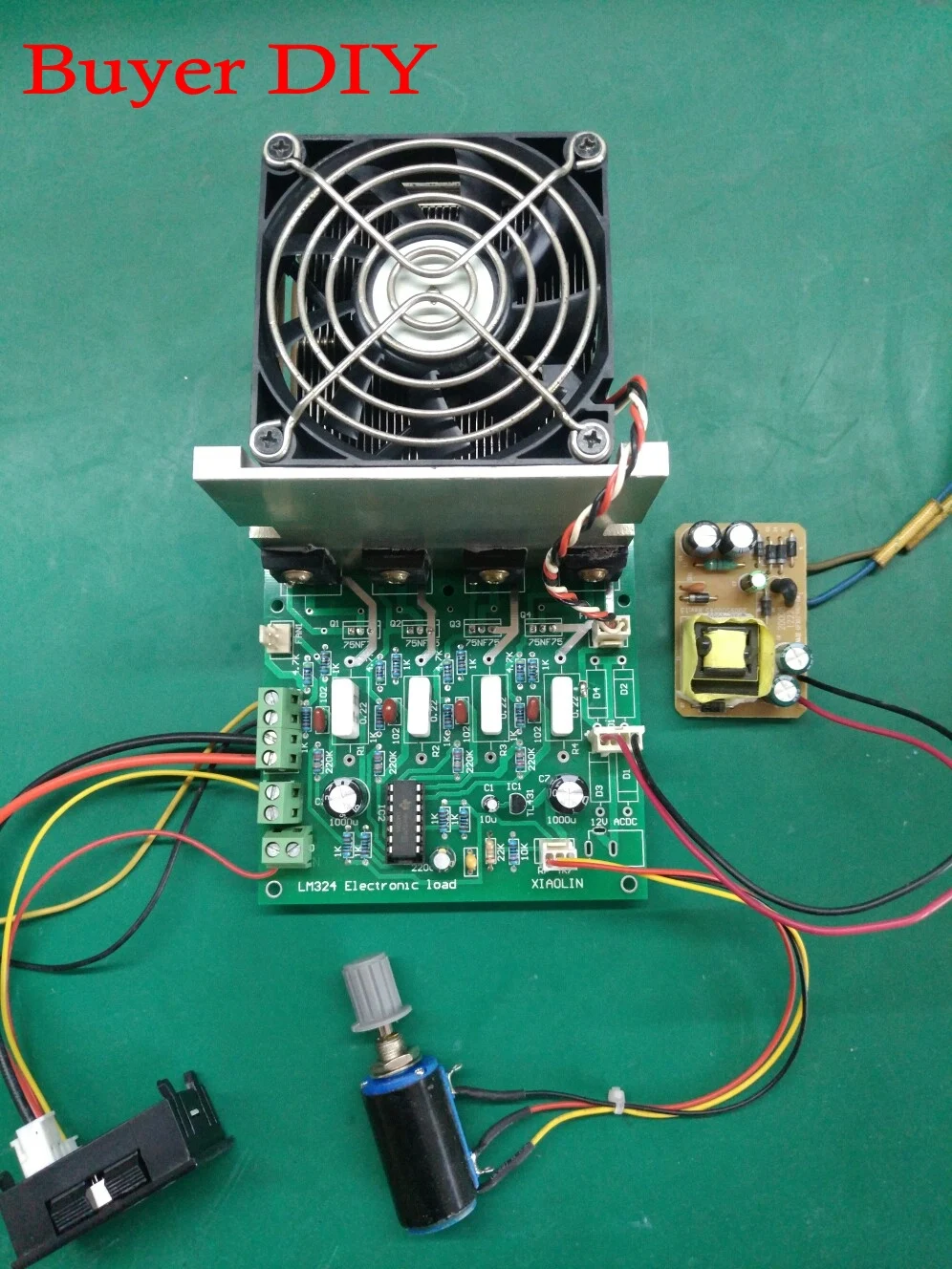
6. Open the cap of the knob and tighten the screw.
7. The power tube is coated with thermal grease and screwed directly to the heat sink, and the heat sink must be connected before power-on debugging! Otherwise, the power tube may be burned out!
Note: The positive and negative poles of the tested power supply must not be reversed, otherwise the MOS power tube will be burned out!
Anti-reverse connection: the anode of the input terminal IN of the board is welded with a high current diode such as 20A10


Reviews
There are no reviews yet.